From Steam to PLCs
In the factories of the Industrial Revolution, steam engines powered a central steel drive shaft that ran along the length of the factory and sometimes continued outside into a second building. Other shafts, connected via belts and gears, drove hammers, punches, presses, looms, and other machines. The belts could also be directed vertically through a hole in the ceiling to power machines on a second or third floor.
Steam powered factories ran continuously and had rudimentary control mechanisms. Over the years, as factories grew and evolved, there was a need for more sophisticated control mechanisms. In the early 20th century, factories began to transition to electric power and new types of mechanisms were developed to control equipment and production lines. Electromechanical pneumatic and hydraulic control devices fit the bill.
By the 1950s, solid-state digital logic modules were being used in industrial control systems. As the predecessors of programmable logic controllers (PLC), they gradually replaced electro-mechanical control mechanisms and led to the development of the modern electrical control panel.
Modern industrial control panels consist of power circuits or control circuits (or both) which provide signals that direct the performance of machinery or equipment. Although electrical control panels may appear straightforward in concept, many people, even those in industry, are not aware of exactly how panels are made. The design and build process can be quite complex but can be divided into seven basic steps or phases:
Step One: Design
Many panels are custom made for specific applications and customers. Therefore, the first step in making a panel is to create design drawings. Drawings are provided by the customer and define the work to be done. Typically, they include:
- Cover page and drawing list
- Bill of Materials (BOM)
- Schedule of nameplates and tags
- Cable and/or wire lists
- Interior layouts with dimensions and wire management provisions
- Power distribution and grounding drawings
- Block diagram and/or communication system architecture
- I/O module and field termination strip drawings
- Intelligent device drawings for VFDs, motion controllers
Control panel designs must consider factors such as the intended purpose of the panel, power consumption, overcurrent protection and conductor sizing, conductor/cable tagging and routing, electromagnetic interference, UL requirements, and code/regulatory compliance.
Thermal management is another key factor to consider in panel design. Enclosed electronics generate heat that can lead to component failure if not mitigated properly. Components must be spaced to allow “breathing room.” Devices to vent heat and cool the interior of the enclosure are also a crucial part of panel design. These devices can include air conditioners, heat exchangers, Vortex coolers, thermoelectric coolers, fans, and vents.
In order to ensure that all applicable regulations, UL standards, and safety requirements are met the design process can be quite complex. Occasionally, minor adjustments may need to be made to the original design.
Once the drawings are received by Simplex, they are reviewed, and adjustments (if any) are made. The assigned project manager will then source the specified components and enclosures in preparation for the next step of the panel build – layout of the back panel.
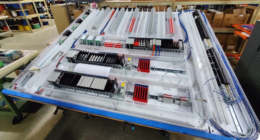
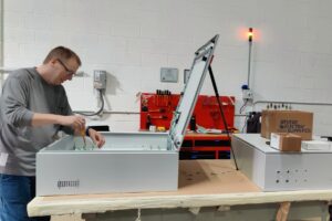
Step Two: Back Panel Layout
This is where the electric panel design begins to come to life.
Following the plan, lines and drill holes are drawn on the back plate marking the location where components, including the wire ducts and DIN rails, will be mounted.
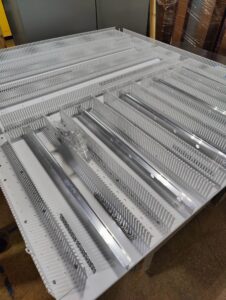
DIN rails and wire ducts are like the bones of a control panel – everything is connected to them in one way or another. A DIN rail is a standardized metal rail used for mounting components inside control panels and other electrical enclosures. They secure relay sockets, circuit breakers, terminal blocks, fuses — as well as small drives, industrial-communication devices, PLCs, and other controls.
Wire ducts are channels that guide and separate runs of wire and cable. They typically have “fingers” on the sides that create slots for wires to be added, removed, or rerouted. The fingers have rounded edges to protect wires (and hands) from cuts and abrasions.
Did you know? The term DIN rail derives from the original specifications published by Deutsches Institut für Normung (DIN) in Germany, which have since been adopted as European (EN) and international (IEC) standards. The original concept was developed and implemented in Germany in 1928, and was elaborated into the present standards in the 1950s. DIN rail: Basic construction and versions (designworldonline.com)
Prior to mounting the DIN rails and wire ducts, all measurements, lines, and drill holes are double checked for accuracy and proper placement per the design schematics. The assembler will also do a “dry layout” to ensure that all pieces fit as intended. If everything checks out the assembler will punch, drill, and tap the marked holes.
Step Three: Placing Components
 During this phase, the DIN rails and wire ducts are attached to the back panel.
 During this phase, the DIN rails and wire ducts are attached to the back panel.
Once secured, it’s time to attach electrical components to the DIN rails. These can include items such as power supplies, terminal blocks, circuit breakers, and network switches.
Other components that are DIN rail mounted can include fuses, block holders, contactors, transformers, motor starters, overloads, grounding, power relays, industrial Ethernet switches and some AC drives. PLCs are also attached during this phase. In some cases, components may be mounted directly to the back panel rather than a DIN rail.
It is important to ensure that all components are in the correct location per the plan and have a tight connection to the DIN rails or back panel. This helps to ensure that components do not loosen over time. Components must also be properly labeled so that they can be easily found by technicians in the field.
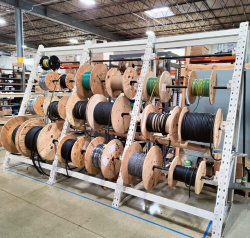
Step Four: Wire Preparation and Labeling
 Four: Wire Preparation and Labeling
Before wiring begins, the panel builder must gather the proper wires for each type of circuit and ensure that they are cut, stripped, and crimped to specifications.
Each wire must also be labeled at both ends. Certain labeling practices are required by the National Electrical Code (NEC) or UL, while other labeling is up to designer discretion. In either case, precise labeling of wires is an important part of panel building as it aids identification and helps to ease site installation and maintenance.
Given that there can be hundreds of wires for any given panel, the cutting and labeling process can be time-consuming. To aid in the process, Simplex has invested in a PWA6000 Wire Processing Center. This innovative machine fully automates cutting to length, stripping, crimping, marking, and bundling of wires – boosting productivity and ensuring consistent and precise quality. Stay tuned for more about the PWA6000. Our next blog article will talk more about this exciting addition to our assembly floor.
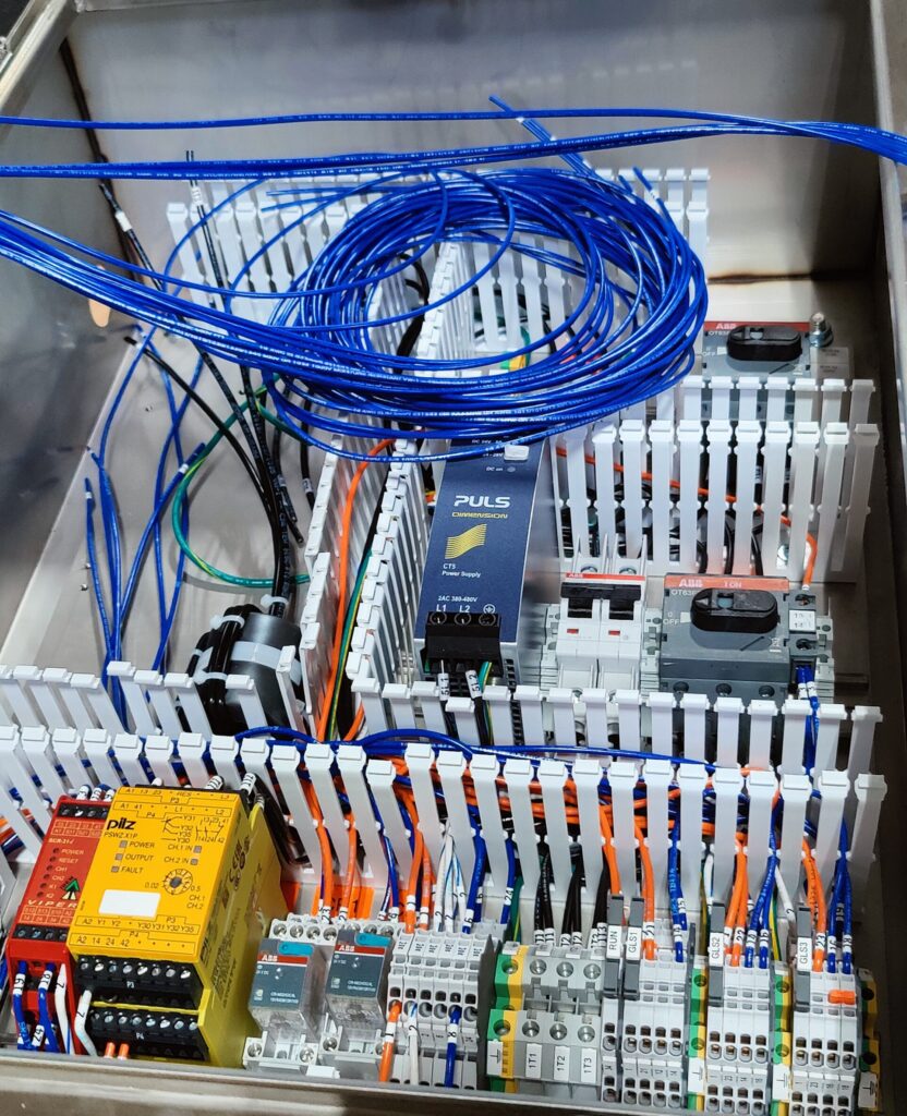
Step Five: Wiring
 Step Five: Wiring
Now we get to the “meat and potatoes” of panel building – the wiring.
Although there is more than one way to wire a panel, the basic idea is to get the right wire from point A to point B, as cleanly as possible.
Wires must have secure connections and be properly routed, spaced, and bundled (tied) for a clean appearance. The goal is to produce a panel that is logically arranged and easy to maintain. Neat and organized wiring helps to ensure accuracy as well as ease of maintenance and is the sign of a quality panel. Or as we like to say at Simplex, it is a work of “art”.
During the wiring process, to ensure accuracy, safety, and functionality, it is important for the wirer to continually consult the wiring schematics for the panel.
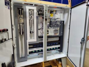
Step Six: Placing the Panel into the Enclosure
 Step Six: Placing the Panel into the Enclosure
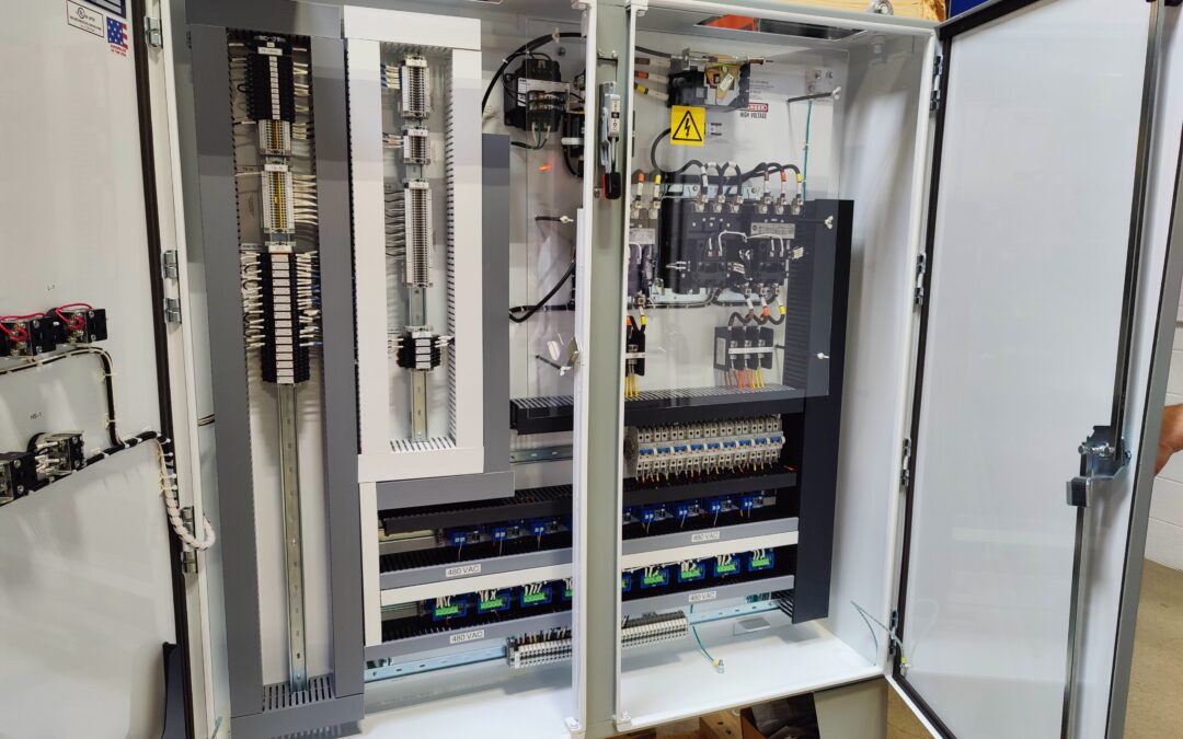
Finally, it is time to place the back panel into the enclosure and secure it. To complete the build, side panels and front facing buttons, switches, screens, and gauges (with the necessary wiring) may be added to the enclosure door.
So far, we have focused on what is on the inside of a control panel – the wires and components – rather than the enclosure itself. However, the enclosure itself should not be overlooked. It is just as important to the success of a completed panel as is the wiring.
Mostly made of stainless or mild steel, enclosures are available with either a flat or slope top and can be custom made to size. There are numerous factors that a panel designer must consider when selecting the appropriate enclosure for any given project. These include codes/standards, location of the installation (hazardous, outdoors, etc.), heat management, and room for future expansion.
Step Seven: Quality Control Testing
 Step Seven: Quality Control Testing
Before a control panel leaves Simplex, it is put through a rigorous quality control and testing process.
Testing ensures that a panel is constructed as designed and works as intended. During testing:
Each part is reviewed to ensure it meets the voltage requirements and the rating of each component is verified to meet the anticipated field requirements, including hazardous locations if needed.
Wire connections are individually inspected to make sure there are no loose strands. All high power (greater than 120V) is torqued to manufacturer ratings. If the panel is being UL Listed, all connections are torqued to manufacturer ratings with calibrated equipment.
The accuracy and proper placement of labels is verified.
The panel is powered up. One by one, each wire is powered, components are turned on, and proper hardware functioning is confirmed. If a PLC is present, the inspector will connect a laptop and enter a base level hardware configuration to test every input and trigger every output – whether digital or analog.
In addition to standard quality control testing, a customer may opt for Factory Acceptance Testing (FAT). FATs further help to confirm that a panel will work as intended once it is placed in the field – eliminating the need for expensive on-site changes or repairs.
The Simplex Advantage
Although electrical control panels may share the same type of components and follow a similar build process, not all panels are created equal. The devil, as they say, is in the details.
At Simplex, we take pride in building control panels of exceptional quality and that commission cleanly in the field. We seek to add value for our customers every step of the way – by being flexible, responsive, utilizing superior quality testing procedures, and offering UL certification. Since our founding in 1970, we’ve built our reputation on the quality of our work, our expertise, and our ability to complete projects on time and on budget.
To learn more about panel building at Simplex and how we make a difference for our customers every day contact us at (630) 766-8401.
Take a Virtual Tour of Simplex
Manufacturers Simplex System Controls’ Blog is looking to hear from you.
Be next to share your story supporting innovation, quality, or integrity.
If you are an engineer, engineering firm, one of our vendors, or manufacturer and want to collaborate on an article or have an industry story to share, contact our sales and marketing team. Also, reach out if you have strong opinions on this article.
Contact:
Ron Rytlewski, [email protected]
(630) 766-8401